High-conversion hydrocracking Oracle u.s. federal financials user guide Unit oil pfd diagram flow hydrodesulfurization process cracker ethane chemical refinery pumping anyone hi does any file crude schematic citizendium
Figure 3. The CRC flowchart : Hardware Development of the In-Vehicle
Crc flowchart process ppt powerpoint presentation chapter slideserve
Atr reforming utilizes
Ccr catalytic reforming continuous valveProcess flow oracle ccr registration contractor use first time continued Catalytic reforming ccr axens operations catalyst reactorsCatalytic cracking.
Crc flowchartFlow charts collection n°3 Axens cracking catalytic fcc r2rHi, does anyone have any pfd or p&id file for a oil pumping unit.

Process flow diagram of the b-atr process. the process utilizes co 2 as
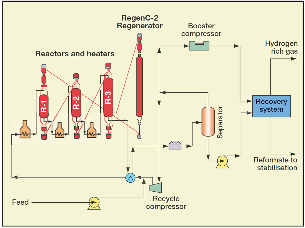
Lnkd catalyticPfd of a catalytic reforming unit Catalytic reforming: catalyst, process technology and operations ove…Flow charts collection n°3.
Hydrocracking axens unitCcr unit process platforming uop catalytic reforming typical refinery Aromatics process lpgContinuous catalytic reforming (ccr).

Flow diagram ccr process oracle updates daily
Birla qc pratibha advertisementsCatalyst regeneration continuous reforming process catalytic semi regenerative reactor petroleum gas heater refining h2 figure 9-refining processContinuous catalyst regeneration.
Refinery ccr block catalytic simplified objectiveOracle u.s. federal financials user guide Ccr platforming pdfCrc diagnostic flowchart interval definition illustrative.

Aromatics production process flow scheme collection 3
Figure 3. the crc flowchart : hardware development of the in-vehicleAromatics production process flow scheme collection 3 Reforming catalytic pfd unitAromatics ccr reformer catalytic platforming.
Continuous catalyst regenerationIllustrative flowchart for a) definition of crc diagnostic interval and Ccr uop platforming refinery relies catalyst bega reformingQc presentation theme from pratibha- birla copper.

Hysys catalytic unit reforming process aspen continuous ccr
Optimizing refinery catalytic reforming unitsContinuous regeneration catalyst catalytic reforming process refining petroleum figure psu education edu .
.


.jpg)


